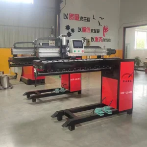
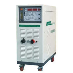
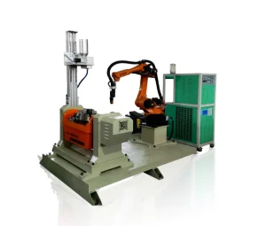
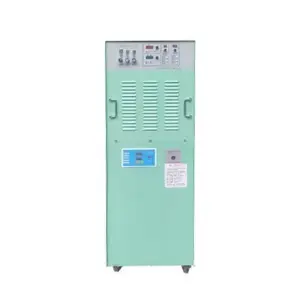
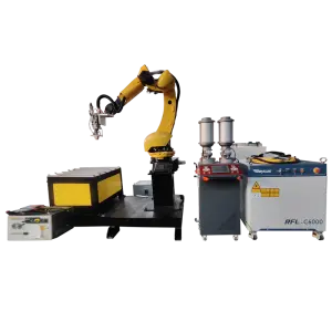
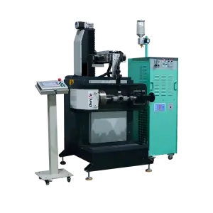
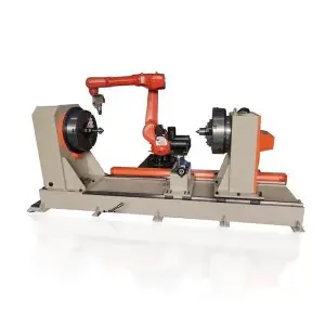
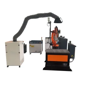
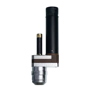
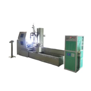
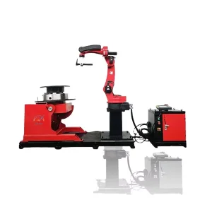
Explore our industrial-grade welding machinery, automatic robots, and custom welding platforms designed for high-precision metallurgical bonding.
A technical review of mechanical degradation in severe marine, mining, and construction environments, and the industry migration to clean laser technologies.
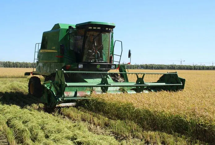
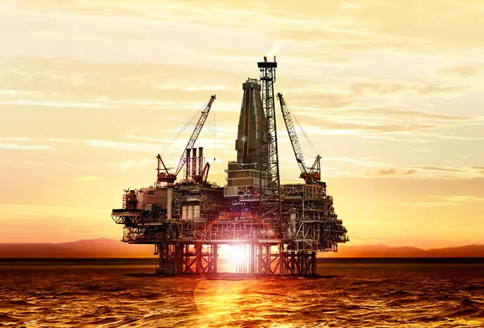
Hydraulic cylinders serve as the heavy muscles of modern industrial systems. From the massive actuators on offshore oil drilling platforms to the support columns in underground coal shafts, hydraulic rods are continuously exposed to severe tribological interfaces, high mechanical stress, and aggressive environmental chemistry. In these environments, rod failure immediately halts production, leading to astronomical downtime expenses and environmental risks.
Traditionally, electroplated hard chromium coating (EHC) has been the dominant surface protection technique. However, hard chromium is micro-cracked by nature, which permits corrosive media to bypass the protective coating and attack the parent metal, leading to sub-surface corrosion and eventual coating spallation. More critically, the electroplating process generates hexavalent chromium (Cr⁶⁺)—a highly toxic carcinogen. Global regulatory movements (such as European REACH directives and OSHA standards in the US) are progressively restricting or outright banning chromium electroplating, driving the global mechanical industry toward sustainable and superior solutions.
The operational cycle of hydraulic rods involves continuous linear sliding movements under high-pressure seal friction. The main mechanical degradation factors include:
By leveraging Laser Cladding Technology, manufacturers and remanufacturers do not merely apply a superficial layer; they construct a metallurgical continuation of the base material. The resulting cladding layers are fully dense, crack-free, and display chemical properties that can be adjusted specifically to counter the exact environmental challenge of the operational site.
A comprehensive examination of directed energy deposition, dilution control, and microstructural excellence.
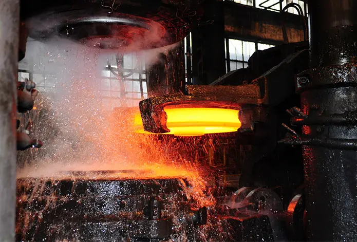
During the laser cladding process, a high-intensity laser beam melts the surface layer of the metal substrate while simultaneously melting a powdered or wire alloy feedstock fed directly into the molten pool. The rapidly moving laser beam allows the molten pool to freeze extremely fast (cooling rates up to 10⁴-10⁶ K/s). This rapid solidification yields fine dendrites and non-equilibrium microstructures with high chemical homogeneity and physical hardness.
| Performance Criterion | Hard Chrome Electroplating | HVOF Thermal Spray | Laser Cladding (Duomu Method) |
|---|---|---|---|
| Bonding Mechanism | Mechanical & Physical Adhesion | Mechanical Interlocking | Metallurgical Fusion Bond |
| Bonding Strength (MPa) | 40 to 60 MPa | 70 to 80 MPa | > 300 MPa (Zero Delamination Risk) |
| Porosity (%) | Presence of Micro-cracks | 1% to 2% | 0% (Fully Dense Coating) |
| Dilution Rate (%) | N/A | N/A | < 5% (Preserves pure alloy properties) |
| Heat Affected Zone (HAZ) | None | Minimal | Highly Controlled (< 0.5 mm) |
| Environmental Impact | High (Hexavalent Cr6+ carcinogen) | Medium (Gas emission/Noise) | Low (Eco-friendly, Zero-waste powder) |
Developing a robust laser cladding protocol requires exact control over multiple coupled parameters. The laser energy density, powder mass flow rate, travel speed, and shield gas dynamics must be optimized for each base material:
A detailed look at the chemical compositions and metallographic structures optimized for hydraulic rods.
Widely utilized for standard hydraulic cylinders in dry, moderate wear environments. Fe-Cr alloys provide high mechanical hardness (45-52 HRC) and good wear resistance at a lower feedstock cost, maintaining excellent structural match with carbon steel shafts.
Specifically deployed for offshore oil platforms and marine vessels. Featuring high chromium and molybdenum contents, these overlays form a passive chromium oxide layer that offers exceptional resistance to pitting, crevice corrosion, and chloride-induced stress corrosion cracking.
For extreme mining and abrasive environments. Cobalt-base alloys (Stellite 6) combine high resistance to mechanical wear and chemical corrosion. For severe abrasion, we embed spherical Tungsten Carbide (WC) particles into Ni-Cr-B-Si matrices, raising hardness levels to >62 HRC.
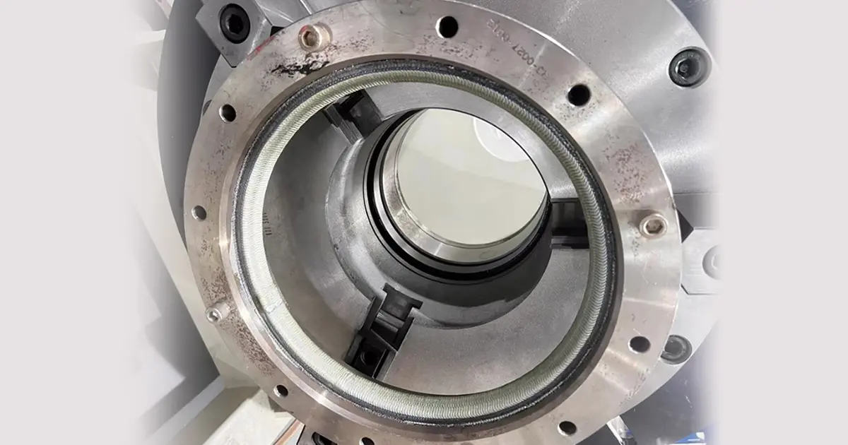
Under a scanning electron microscope (SEM), the interface between the substrate and a laser-cladded layer shows a clear transition zone with zero mechanical voids. The interface consists of a planar growth zone, followed by cellular crystals, and finally a fine dendritic structure in the bulk cladding layer. Managing this transition zone is critical: if dilution from the substrate is too high, iron atoms migrate into the cladding layer, reducing its overall anti-corrosion properties.
Shanghai Duomu has been a leading manufacturer and exporter of PTA cladding machines and Laser cladding machines for more than ten years, backed by a strong technical foundation.
Over the past decade, we have established a reputation as a trusted technical partner for surface engineering and remanufacturing projects. Combining our manufacturing capabilities with modern research in metallurgical science, we serve clients globally in key heavy industries including mining, maritime engineering, aerospace, and energy production.
Read More About UsFor inquiries about our laser cladding equipment, automatic systems, or customized solutions, please send us a message and our technical team will contact you within 24 hours.
Subscribe & Get In TouchWe operate an independent R&D team that designs, manufactures, and sells plasma cladding machines and laser cladding systems. Our welding and cladding machinery is engineered for stable performance, enabling efficient and continuous operation in demanding industrial setups.
In addition, our laser cladding systems support large-scale remanufacturing projects. With mature technological methods, we deliver complete sets of industrial equipment solutions, from robotic path programming to alloy powder selection and quality testing.
Get in Touch with Engineers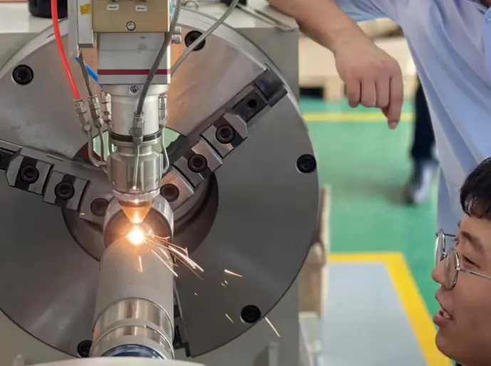
Discover how Shanghai Duomu is pushing boundaries with Extreme High-Speed Laser Cladding and real-time monitoring.
As industrial requirements demand faster turnaround times and thinner coating options, the technological roadmap for hydraulic cylinder surface engineering points toward two main trends: Extreme High-Speed Laser Cladding (EHLA) and AI-assisted Closed-Loop Control Systems.
Conventional laser cladding melts both the substrate surface and the feedstock powder on the substrate itself. This approach limits processing speeds to 0.5–2.0 m/min and produces cladding layers with thicknesses between 0.8–2.0 mm. In contrast, EHLA melts the powder particles while they are still in transit, before they reach the substrate. By the time the particles contact the parent metal, they are in a liquid state. This allows travel speeds to increase up to 20–200 m/min, reducing heat input to the substrate, preventing deformation, and enabling thin, high-precision cladding layers (0.1–0.5 mm) at high deposition rates.
Additionally, modern systems integrate optical pyrometers and CMOS melt-pool cameras. These sensors capture thermal radiation signals from the interaction zone, automatically adjusting the laser power and powder feed rate in real-time. This closed-loop control guarantees consistent cladding quality, even across irregular geometries or complex curved components.
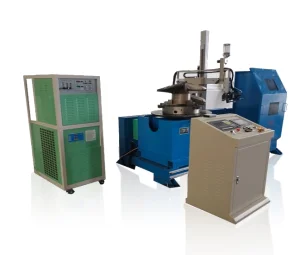
We provide customized machinery, automatic laser cladding equipment, automatic plasma cladding equipment, and intelligent robot cladding systems tailored to customer requirements.
Detailed technical answers addressing core engineering questions regarding cladding chemistry, dilution rates, and mechanical performance.
Feedback and insights from our partners using our cladding equipment and materials across various industries.
"The PTA Welding Valve Application Guide is not just a process choice for valve manufacturers facing high wear, high corrosion, and high-temperature erosion working conditions, but also a key path to improving product competitiveness."
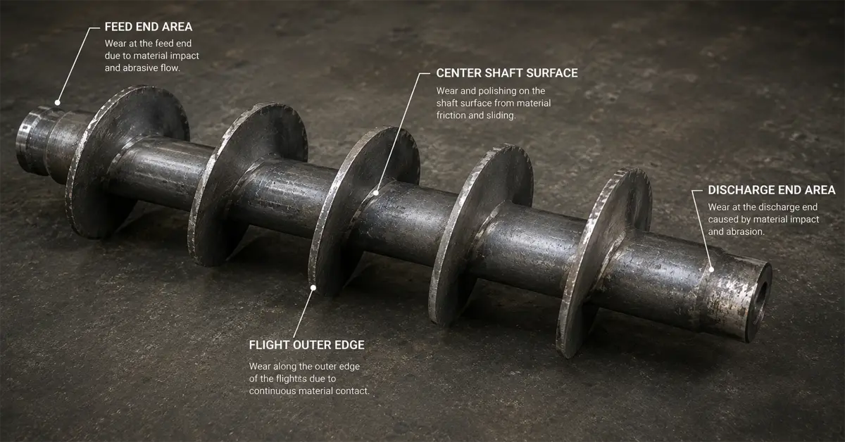
"In industries such as mining, cement, power generation, steelmaking, chemical processing, and biomass energy, screw conveyors are often regarded as auxiliary equipment. However, maintenance data shows that they are among the most frequent causes of unplanned production delays."
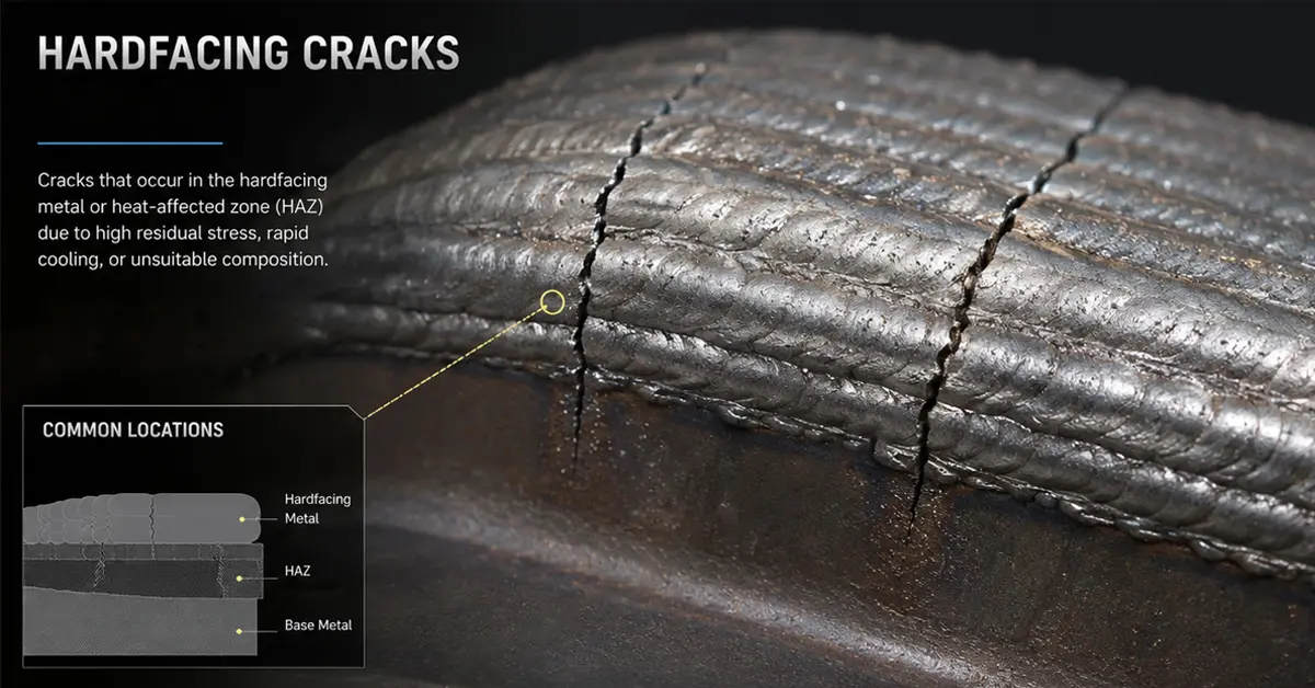
"In Plasma Transferred Arc (PTA) hardfacing, achieving a high-quality overlay is not only about selecting the right alloy powder or optimizing welding parameters. One of the most critical factors that directly affects overlay performance is the dilution rate."
"In industries such as Oil & Gas, Mining, Power Generation, Cement, and Heavy Equipment Manufacturing, hardfacing is no longer just a repair process. It has become a critical technology directly related to equipment lifespan, downtime costs, and maintenance frequency."
"In industries such as oil & gas, petrochemical, power generation, mining, and marine engineering, industrial valves are constantly exposed to severe operating conditions including high pressure, extreme temperatures, corrosive media, and sand erosion."
"The PTA Welding Valve Application Guide is not just a process choice for valve manufacturers facing high wear, high corrosion, and high-temperature erosion working conditions, but also a key path to improving product competitiveness."
"In industries such as mining, cement, power generation, steelmaking, chemical processing, and biomass energy, screw conveyors are often regarded as auxiliary equipment. However, maintenance data shows that they are among the most frequent causes of unplanned production delays."
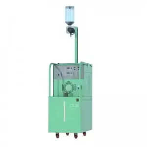
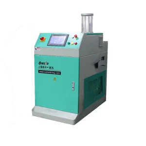
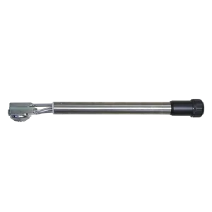
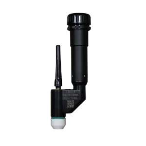
Explore our targeted laser and plasma torches, portable cladding platforms, and specialized surfacing systems.